1N4728AG thru 1N4764AG, e3 (Glass)
Silicon 1 Watt Zener Diodes
SCOTTSDALE DIVISION
APPEARANCE
The popular 1N4728AG thru 1N4764AG glass body series of 1.0 watt
Zeners provides voltage regulation in a selection from 3.3 to 100 volts in
5% tolerances with other tighter tolerances also available as identified by
different suffix letters on the part number. These glass encapsulated
Zeners with a G suffix provide hermetic-sealed qualities and higher rated
temperature when required beyond that optionally provided in the same
size DO-41 plastic-body (P suffix) for these JEDEC part numbers. Both of
these package options are available by Microsemi including RoHS
Compliant devices with an “e3” suffix. A variety of other Zener product
offerings and packages are available by Microsemi to meet higher and
lower power or test current applications.
DO-41 or
DO-204AL
(Glass)
WWW . Microsemi .C OM
DESCRIPTION
IMPORTANT: For the most current data, consult MICROSEMI’s website: http://www.microsemi.com
FEATURES
APPLICATIONS / BENEFITS
• JEDEC registered 1N4728A to 1N4764A
• Options for screening in accordance with MIL-PRF19500 for JAN, JANTX, JANTXV, and JANS are
available by adding MQ, MX, MV, or MSP prefixes
respectively to part numbers.
• Surface mount equivalents available as SMAJ4728A to
SMAJ4764A and MLL4728A to MLL4764A (consult
factory for others)
• Plastic body axial-leaded Zener equivalents are also
available as 1N4728AP to 1N4764AP
• RoHS Compliant devices available by adding “e3” suffix
•
•
•
•
•
•
•
MAXIMUM RATINGS
MECHANICAL AND PACKAGING
•
•
•
•
•
•
•
CASE: Hermetically sealed axial-lead glass package
TERMINALS: Tin-Lead (Sn/Pb) or RoHS Compliant
annealed matte-Tin plated solderable per MIL-STD750, method 2026
POLARITY: Cathode indicated by band. Diode to
be operated with the banded end positive with
respect to the opposite end for Zener regulation
MARKING: Part number
TAPE & REEL option: Standard per EIA-296 (add
“TR” suffix to part number)
WEIGHT: 0.4 grams
See package dimensions on last page
Microsemi
Scottsdale Division
8700 E. Thomas Rd. PO Box 1390, Scottsdale, AZ 85252 USA, (480) 941-6300, Fax: (480) 947-1503
Page 1
1N4728AG-1N4764AG,e3
• Power dissipation at 25 C: 1.0 watts (also see
derating in Figure 1).
• Operating and Storage temperature: -65ºC to +175ºC
º
• Thermal Resistance: 80 C/W junction to lead at 3/8
(10 mm) lead length from body, or 140ºC/W junction
to ambient when mounted on FR4 PC board (1 oz
Cu) with 4 mm2 copper pads and track width 1 mm,
length 25 mm
• Steady-State Power: 1.0 watts at TL < 95oC 3/8 inch
(10 mm) from body or 1.00 watt at TA < 35ºC when
mounted on FR4 PC board as described for thermal
resistance above (also see Figure 1)
• Forward voltage @200 mA: 1.2 volts (maximum)
º
• Solder Temperatures: 260 C for 10 s (max)
º
Copyright © 2005
10-18-2005 REV C
Regulates voltage over a broad operating current
and temperature range
Extensive voltage selection from 3.3 to 100 V
Flexible axial-lead mounting terminals
Standard voltage tolerances are plus/minus 5% with
A suffix and 10 % with no suffix identification
Tight tolerances available in plus or minus 2% or 1%
with C or D suffix respectively
Nonsensitive to ESD per MIL-STD-750 Method 1020
Hermetically sealed glass body construction
�1N4728AG thru 1N4764AG, e3 (Glass)
Silicon 1 Watt Zener Diodes
SCOTTSDALE DIVISION
JEDEC
TYPE
NUMBER
(Note 1)
1N4728A
1N4729A
1N4730A
1N4731A
1N4732A
1N4733A
1N4734A
1N4735A
1N4736A
1N4737A
1N4738A
1N4739A
1N4740A
1N4741A
1N4742A
1N4743A
1N4744A
1N4745A
1N4746A
1N4747A
1N4748A
1N4749A
1N4750A
1N4751A
1N4752A
1N4753A
1N4754A
1N4755A
1N4756A
1N4757A
1N4758A
1N4759A
1N4760A
1N4761A
1N4762A
1N4763A
1N4764A
ZENER
VOLTAGE
(Note 4)
TEST
CURRENT
MAXIMUM
DYNAMIC
IMPEDANCE
(Note 2)
MAXIMUM
REVERSE
CURRENT
TEST
VOLTAGE
(Vz)
(IZT)
(ZZT @ IZT)
(IR @ VR)
(VR)
VOLTS
3.3
3.6
3.9
4.3
4.7
5.1
5.6
6.2
6.8
7.5
8.2
9.1
10
11
12
13
15
16
18
20
22
24
27
30
33
36
39
43
47
51
56
62
68
75
82
91
100
mA
76
69
64
58
53
49
45
41
37
34
31
28
25
23
21
19
17
15.5
14
12.5
11.5
10.5
9.5
8.5
7.5
7.0
6.5
6.0
5.5
5.0
4.5
4.0
3.7
3.3
3.0
2.8
2.5
OHMS
10
10
9
9
8
7
5
2
3.5
4.0
4.5
5.0
7
8
9
10
14
16
20
22
23
25
35
40
45
50
60
70
80
95
110
125
150
175
200
250
350
μA
100
100
50
10
10
10
10
10
10
10
10
10
10
5
5
5
5
5
5
5
5
5
5
5
5
5
5
5
5
5
5
5
5
5
5
5
5
VOLTS
1
1
1
1
1
1
2
3
4
5
6
7
7.6
8.4
9.1
9.9
11.4
12.2
13.7
15.2
16.7
18.2
20.6
22.8
25.1
27.4
29.7
32.7
35.8
38.8
42.6
47.1
51.7
56.0
62.2
69.2
76.0
MAXIMUM
REGULATOR
CURRENT
TA = 50oC
MAXIMUM
KNEE
IMPEDANCE
(Note 2)
TEST
CURRENT
MAXIMUM
(SURGE)
CURRENT
(Note 3)
(IZM)
(ZZK @ IZK)
(IZK)
(IS)
mA
276
252
234
217
193
178
162
146
133
121
110
100
91
83
76
69
61
57
50
45
41
38
34
30
27
25
23
22
19
18
16
14
13
12
11
10
9
OHMS
400
400
400
400
500
550
600
700
700
700
700
700
700
700
700
700
700
700
750
750
750
750
750
1000
1000
1000
1000
1500
1500
1500
2000
2000
2000
2000
3000
3000
3000
mA
1.0
1.0
1.0
1.0
1.0
1.0
1.0
1.0
1.0
0.5
0.5
0.5
0.25
0.25
0.25
0.25
0.25
0.25
0.25
0.25
0.25
0.25
0.25
0.25
0.25
0.25
0.25
0.25
0.25
0.25
0.25
0.25
0.25
0.25
0.25
0.25
0.25
mA
1380
1260
1190
1070
970
890
810
730
660
605
550
500
454
414
380
344
304
285
250
225
205
190
170
150
135
125
115
110
95
90
80
70
65
60
55
50
45
WWW . Microsemi .C OM
ELECTRICAL CHARACTERISTICS*
*JEDEC Registered Data
NOTES:
1.
3.
4.
Copyright © 2005
10-18-2005 REV C
Microsemi
Scottsdale Division
8700 E. Thomas Rd. PO Box 1390, Scottsdale, AZ 85252 USA, (480) 941-6300, Fax: (480) 947-1503
Page 2
1N4728AG-1N4764AG,e3
2.
The JEDEC type numbers shown with an A suffix have a 5% tolerance on nominal zener voltage. No suffix signifies a 10% tolerance,
C signifies 2%, and D signifies 1% tolerance. Also add a G suffix for designating glass construction (P suffix designates plastic body
options described by separate data sheet)..
The Zener impedance is derived from the 60 Hz ac voltage that results when an ac current having an rms value equal to 10% of the dc
Zener current (IZT or IZK) is superimposed on IZT or IZK. Zener impedance is measured at two points to ensure a sharp knee on the
breakdown curve and eliminate unstable units. See MicroNote 202 for zener impedance variation with different operating currents.
o
The reverse surge current is measured at 25 C ambient using a ½ square wave or equivalent sine wave pulse 1/120 second duration
superimposed on IZT.
Zener voltage (VZ) is measured at TL = 25ºC (+8, -2ºC) and 90 seconds after application of dc current.
�1N4728AG thru 1N4764AG, e3 (Glass)
Silicon 1 Watt Zener Diodes
SCOTTSDALE DIVISION
TA
on FR4
PC board
o
TL, LEAD TEMP. ( C) 3/8” from body
or TA on FR4 PC Board
FIGURE 1
Power Derating Curve
TEMPERATURE COEFFICIENT mV/oC
RATED POWER DISSIPATION - W
TL
WWW . Microsemi .C OM
GRAPHS
NOMINAL ZENER VOLTAGE (VOLTS)
FIGURE 2
Temp. Coeff. vs. Zener Voltage
FIGURE 3
Capacitance vs. Voltage
for Representative Types
PACKAGE DIMENSIONS (DO-41 or DO-204AL)
1N4728AG-1N4764AG,e3
Copyright © 2005
10-18-2005 REV C
Microsemi
Scottsdale Division
8700 E. Thomas Rd. PO Box 1390, Scottsdale, AZ 85252 USA, (480) 941-6300, Fax: (480) 947-1503
Page 3
�
很抱歉,暂时无法提供与“1N4739 G”相匹配的价格&库存,您可以联系我们找货
免费人工找货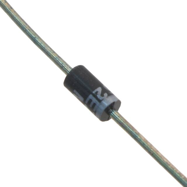


 工商网监
湘ICP备2023018690号
工商网监
湘ICP备2023018690号
